AWS A2.4 Section 7 · AWS D1.1:2025 Figure 5.1

Groove Weld Symbol

Groove weld symbols in AWS A2.4 Section 7 identify prepared joints, dimension placement, and CJP/PJP intent. AWS A2.4 Figure 4.1 lists the groove family, while AWS D1.1:2025 Figure 5.1 supplies prequalified structural CJP joint details for production drawings in steel fabrication today.

All 11 groove weld types per D1.1:2025 Figures 5.1 and 5.2 (AWS A2.4 Figure 4.1 has 8 groove weld symbols). How to read CJP vs PJP from the symbol, dimension placement rules, and D1.1:2025 prequalified joint details.
Ask Flux
Groove Weld Types — Overview
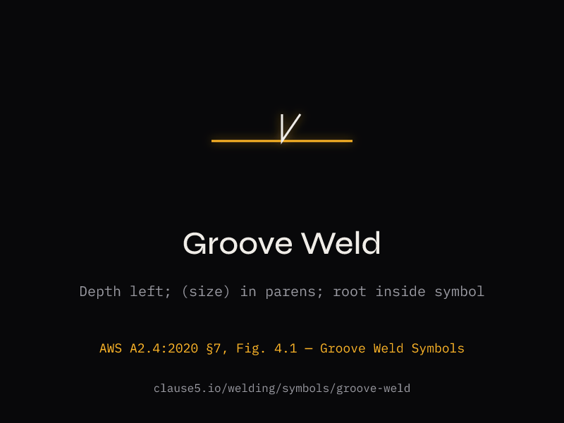
V-Groove
Bevel
Square
J-Groove
CJP vs PJP: No groove depth (D) and no weld size (S) on a groove symbol = CJP (A2.4 7.2.2). A weld size (S) in parentheses that extends only partly through the joint = PJP (7.2.3). Parentheses alone do not mean PJP: CJP double-groove welds may also show their sizes in parentheses (7.2.4).

Groove Weld Application Diagrams

These diagrams show how groove weld dimensions are placed on the symbol and how they correspond to the actual joint cross-section.

no D, no (S) = CJP
Fig 7.1(D) — CJP, no dimensions
(1/2) (S) partial = PJP
Fig 7.1(F) — PJP, weld size in parens
3/8 (3/4) 1/8 60 ° D top, (S) below, root inside, angle outside
Fig 7.2 — Combined dimensions
5/8 (3/8) 1/4 groove + reinforcing fillet
Fig 7.6 — Groove + fillet combo
3/8 60 ° BACKGOUGE 1st ref line: weld 2nd ref line: backgouge (dashed = 2nd operation)
Fig 7.19 — Backgouging sequence

Where Each Dimension Goes

Per AWS A2.4 §7, all groove weld dimensions appear on the same side of the reference line as the weld symbol.

Dimension Location CJP/PJP
D (groove depth) To the LEFT of the symbol, no parentheses PJP only — omitted for CJP
(S) (weld size) To the LEFT, in parentheses PJP (7.2.3); also CJP double-groove sizes (7.2.4)
R (root opening) INSIDE the symbol Both CJP and PJP
α (groove angle) ABOVE or BELOW the symbol (per AWS A2.4 Section 7.3.2) Both CJP and PJP
Length To the RIGHT of the symbol Both CJP and PJP
Common confusion: D (groove depth) and (S) (weld size) are not the same thing. D is how deep you cut the groove. (S) is the effective weld throat for strength calculations. For many joints, D ≥ S. The number without parentheses is D; with parentheses is (S).

Groove Weld Type Reference

D1.1 Type Name Symbol Shape
1 Square groove Two parallel vertical lines
2 Single-V groove V-shape (symmetric)
3 Double-V groove X-shape (V on both sides)
4 Single-bevel groove One vertical + one angled line
5 Double-bevel groove K-shape
6 Single-U groove U-shape (curved bottom)
7 Double-U groove Two U-shapes back to back
8 Single-J groove One vertical + one J-curve
9 Double-J groove Two J-shapes
10 Flare-bevel groove One curved + one vertical line
11 Flare-V groove Two curved lines

Note: The edge weld symbol is classified separately from groove welds under A2.4 Clause 13.

Prequalified Joint Details

D1.1:2025 organizes prequalified groove weld joints into figures. These joints have been tested and approved — using one means you can write a WPS directly without running qualification tests.

Figure Content Key Detail
Figure 5.1 Prequalified CJP groove welded joint details Types 1-9; processes and allowed welding positions are set per joint detail (e.g. SAW B-U2-S and TC-U4b-S: flat only)
Figure 5.2 Prequalified PJP groove welded joint details As Detailed + As Fit-Up tolerances
Figure 5.3 Prequalified fillet weld joint details Not groove — see fillet page
Figure 5.4 Prequalified skewed T-joint details Dihedral angle Ψ: Details A and B 60° min to 135° max; Detail C over 100°; Detail D 30° ≤ Ψ < 60°
Joint designation: Each prequalified joint has a designation like B-U2a (butt, unlimited thickness, single-V, with backing). This designation must appear on the WPS — “single-V groove butt joint” alone is not sufficient.

Under D1.1:2025 5.4.1, CJP groove welds detailed in Figure 5.1 may be used without performing the WPS qualification test described in Clause 6, subject to the limitations in 5.4.1.1 through 5.4.1.9. For a WPS to be prequalified it must conform to all applicable requirements of Clause 5; a WPS that does not conform may be qualified by tests in conformance with Clause 6 (5.1), documented in the test record that proves a welding procedure works. Either way, the parameters are recorded in a written welding procedure that governs production welding.

"CJP groove welds which may be used without performing the WPS qualification test described in Clause 6 shall be as detailed in Figure 5.1 and are subject to the limitations described in 5.4.1.1 through 5.4.1.9."

— AWS D1.1/D1.1M:2025 Clause 5.4.1, Complete Joint Penetration (CJP) Groove Weld Details
Groove Weld Configurations — A2.4 Figures 7.1–7.19
no D, no (S) = full penetration
CJP — no dimensions per §7.2.2
3/4 (3/8) D no parens, (S) in parens
PJP — D and (S) per §7.2.6
1/4 R inside symbol
Root opening — R per §7.3.1
45° angle outside symbol
Groove angle — per §7.3.2
3/8 (1/4) 1/4 groove + reinforcing fillet
Combined groove+fillet — Fig 7.6
BG backgouge in tail
Backgouging — Fig 7.19, §7.11
CJP vs PJP rule (A2.4 §7.2.2 to 7.2.5): No groove depth and no weld size on the symbol = CJP (§7.2.2). A number in parentheses (S) = groove weld size: PJP when it extends only partly through the joint (§7.2.3); CJP double-groove welds may also carry their sizes in parentheses (§7.2.4). A number without parentheses = groove depth D (§7.2.5). These are not interchangeable.

Groove Weld Symbol FAQ

What is a groove weld symbol?
A groove weld symbol indicates a weld made in a groove between workpieces. AWS A2.4 Figure 4.1 defines 8 groove symbol types: square, V, bevel, U, J, flare-V, flare-bevel, and scarf (brazing only). Each can be applied as single-groove or double-groove to cover the commonly referenced configurations (square, single/double-V, single/double-bevel, single/double-U, single/double-J, flare-V, flare-bevel). The shape of the symbol on the reference line represents the joint preparation geometry. For example, a V-groove weld uses a V-shaped symbol, while a J-groove uses a J-shaped symbol. Groove welds are the primary way to achieve complete joint penetration (CJP) in structural steel. The choice of groove type depends on plate thickness, welding position, and access: single-V is common for shop welds, while single-bevel is preferred for field erection where only one side is accessible.
How do you tell CJP from PJP on a groove weld symbol?
Start with the dimensions to the left of the weld symbol. Omitting the groove depth (D) and weld size (S) from the symbol requires a CJP groove weld extending through the thickness of the joint (A2.4 7.2.2). Alternatively, CJP may appear in the tail of the welding symbol. A PJP groove weld shows the weld size (S) in parentheses to the left of the symbol (7.2.3) — e.g. (3/8) means 3/8 in. effective weld size. Parentheses alone do not mean PJP: for double-groove welds that extend completely through the joint, the sizes are also placed in parentheses (required when the two sides differ, optional when they match, per 7.2.4), so compare the sizes with the joint thickness. If you see a number without parentheses to the left, that is the groove depth D, not the weld size. For example, on a single-bevel symbol: 3/4 (no parentheses) to the left means 3/4 in. groove depth, while (3/8) means 3/8 in. PJP effective throat. This distinction is critical for fabricators sizing their weld joint preparation.
Where do groove weld dimensions go on the symbol?
Per AWS A2.4 §7, all groove weld dimensions go on the same side of the reference line as the weld symbol. Groove depth (D) goes to the left without parentheses. Weld size (S) goes to the left in parentheses. Root opening (R) goes inside the symbol. Groove angle goes above or below the weld symbol as appropriate (A2.4 §7.3.2). For example, a single-V groove weld with 45° groove angle, 1/4 in. root opening, and 5/8 in. effective weld size would show: (5/8) to the left in parentheses (weld size), the V symbol, 1/4 inside the symbol (root opening), and 45 above/below (groove angle per §7.3.2). For CJP, D and S are normally omitted (7.2.2); a CJP double-groove weld may instead show its sizes in parentheses (7.2.4). For double-groove joints, each groove is dimensioned independently on its respective side of the reference line.
What are D1.1 prequalified groove weld joints?
D1.1:2025 Figure 5.1 contains prequalified CJP groove welded joint details — joint configurations that have been tested and approved for use without requiring a separate procedure qualification record (PQR). Each joint has a designation (e.g. B-U2a for a single-V butt joint, TC-U4b for a single-bevel-groove T- or corner joint welded with backgouging), specified groove angle, root opening, root face, and approved welding positions. B-U2a, for example, is one of the most commonly used butt joint details; its SMAW rows allow all positions at a 1/4 in. root opening with a 45° groove angle, and flat, vertical, and overhead at 3/8 in. (30°) and 1/2 in. (20°). Figure 5.2 covers prequalified PJP joints. Using a prequalified joint detail per Clause 5.4.1 means you can write a WPS directly from the figure without running qualification tests, saving weeks and thousands of dollars in qualification costs.

Get the groove-weld symbol chart

All 11 groove types plus the full A2.4 symbol reference in one printable PDF — we’ll email it, free.