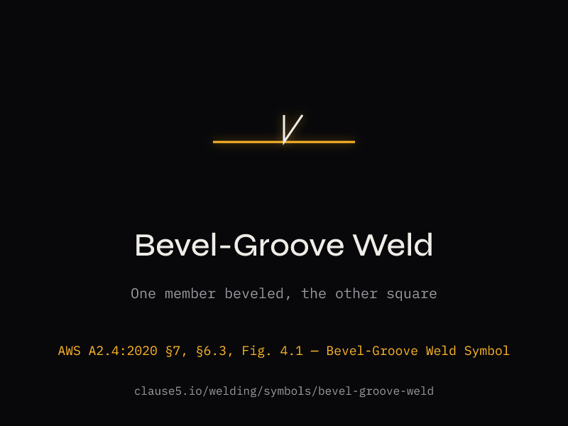
Bevel Groove Weld Symbol
Bevel groove weld symbols identify a single prepared member, so AWS A2.4 uses the broken arrow when only one side is beveled. D1.1:2025 Figure 5.1 then controls the prequalified single-bevel CJP root opening, groove angle, position, backing, and backgouging combinations.
Which Member Gets the Bevel?
The broken arrow is the most important — and most commonly misunderstood — convention in welding symbol reading. Per A2.4 §6.4.1:
Broken arrow (kinked) — the arrow has a visible bend or kink in its shaft. It points at the member that must receive the edge preparation. The fabricator has no choice — that specific member gets beveled.
Straight arrow — per A2.4 §7.1.3.2, a straight arrow means either member may have the desired edge shape. The fabricator can choose which member to bevel based on access, material thickness, or shop preference.
The broken arrow applies to all asymmetric groove types: bevel groove, J-groove, and flare-bevel groove. It does NOT apply to symmetric types like V-groove, U-groove, or flare-V groove.
Prequalified Single-Bevel CJP Details
| Process | Designation | Root Opening | Groove Angle | Positions |
|---|---|---|---|---|
| SMAW | B-U4a | 1/4" | 45° | All |
| SMAW | B-U4a | 3/8" | 30° | All |
| GMAW/FCAW | B-U4a-GF | 3/16" | 30° | All |
| SAW | B-U4a-S | 1/4" | 45° | F only |
| SAW (backgouge) | B-U4b-S | 0 | 60° | F only |
TC-U4a — T-Joint and Corner Joint Variants
| Process | Designation | Root Opening | Groove Angle | Positions |
|---|---|---|---|---|
| SMAW | TC-U4a | 1/4" | 45° | All |
| SMAW | TC-U4a | 3/8" | 30° | F, V, OH |
| GMAW/FCAW | TC-U4a-GF | 3/16" | 30° | All (gas req.) |
| GMAW/FCAW | TC-U4a-GF | 3/8" | 30° | F only |
| GMAW/FCAW | TC-U4a-GF | 1/4" | 45° | All |
| SAW | TC-U4a-S | 3/8" | 30° | F only |
| SAW | TC-U4a-S | 1/4" | 45° | — |
These TC-U4a variants are prequalified CJP T/corner joint details per D1.1:2025 Figure 5.1 and Cl. 5.4.1. U = unlimited thickness. The T-joint callout below applies to these variants.
The Dashed Fillet on TC-U4a — Contouring vs. Reinforcing (D1.1 Cl. 4.8.5)
D1.1 uses two similar terms for fillets over groove welds: contouring (Cl. 4.8.5, CJP or PJP) and reinforcing (Cl. 4.5.2.7, PJP only). Mixing them invokes the wrong clause. The dashed fillet on Figure 5.1 TC-U4a is a contouring fillet.
Contouring Fillet — CJP or PJP, Cl. 4.8.5
Per Cl. 4.8.5, contouring fillets apply over CJP or PJP groove welds in butt, corner, and T-joints to contour the weld face. In statically loaded applications, the size need not exceed 5/16 in [8 mm] — guidance, not a cap. Natural reinforcement on CJP T/corner groove welds is non-rejectable.
Cl. 4.8.5, the fillet-like reinforcement naturally forming on CJP T/corner groove welds "shall not be cause for rejection nor need it be removed provided it does not interfere with other elements of the construction." Not a defect.
Reinforcing Fillet — PJP only, Cl. 4.5.2.7
Per Cl. 4.5.2.7, a reinforcing fillet sits over a PJP groove to reinforce the effective throat. For most PJP details, effective throat = shortest distance from root to fillet face, minus 1/8 in [3 mm]. For PJP flare bevel, use Table 4.1. Allowable stress = PJP stress per Cl. 4.7.3.6. Never applies to CJP.
The 1/4 in [6 mm] Minimum at Reentrant Corners — Cl. 4.18.3
Cl. 4.18.3 imposes a hard minimum: in transverse corner and T-joints subject to tension or bending, a single pass contouring fillet weld not less than 1/4 in [6 mm] shall be added at reentrant corners. Cl. 4.8.5's static guidance covers a different regime.
The Dashed Element on D1.1 Figure 5.1 TC-U4a
Figure 5.1 details prequalified CJP joints (Cl. 5.4.1). For TC-U4a variants, the dashed fillet triangle in the symbol inset is the optional contouring fillet per Cl. 4.8.5 — not a reinforcing fillet.
| Property | Contouring Fillet | Reinforcing Fillet |
|---|---|---|
| Code clause | Cl. 4.8.5 | Cl. 4.5.2.7 + 4.7.3.6 |
| Joint type | CJP (also PJP) | PJP only |
| Purpose | Contour weld face | Reinforce PJP effective throat |
| Min size (reentrant corner, tension) | 1/4 in [6 mm], single pass (Cl. 4.18.3) | N/A |
On a CJP T-joint or corner joint, a small fillet-like reinforcement at the toe is expected and non-rejectable. Calling it a "reinforcing fillet" in an inspection report invokes Cl. 4.5.2.7 effective-throat rules — which do not apply to a CJP weld.
Clause5 CWI reviewer
For the CJP vs PJP decision framework, see the CJP weld guide. For effective-throat calculations, use the fillet weld size calculator.
CWI Exam Mnemonic: Reinforcing = PJP. Contouring = CJP. The "R" and "C" map to the joint type.
Same Side or Opposite Sides? Combination Symbols vs Two-Side Welds
The first question to ask before drawing a combination symbol is whether the two welds go on the same side of the joint (e.g., a single bevel groove with a contouring or reinforcing fillet stacked on top, both inside a T-joint corner) or on opposite sides of the joint (e.g., a corner joint with a bevel groove inside and a 1/4 in [6 mm] fillet on the outside). The two cases use different A2.4 conventions, and confusing them is the most common error in stacked-symbol drafting.
Same Side — Combination Symbol per A2.4 §6.5 / Figure 6.3
Per A2.4 §6.5, joints requiring more than one weld type on the same side use a combination weld symbol — multiple weld symbols stacked on a single reference line. Figure 6.3 shows the canonical examples: backing plus single-J plus fillet (A); double-bevel-groove plus fillet (B); single-bevel-groove plus double fillet (C); double-square-groove plus double fillet (D). When stacked, the symbols share their perpendicular legs with the reference line, and all symbols on the same side of the line apply to the same side of the joint per §6.2.
The single-bevel CJP T/corner detail with a dashed contouring fillet (D1.1 Figure 5.1, joint TC-U4a) is the welding-code example of this same-side stacking — the bevel groove and the contouring fillet both serve the same side of the joint, the inside of the T or corner. See the contouring vs reinforcing section above for the D1.1-side detail.
Opposite Sides — Two Symbols on Opposite Sides of the Reference Line
When the joint requires welds on both sides — e.g., a corner joint with a single-bevel groove on the inside and a 1/4 in [6 mm] fillet on the outside — the symbols are NOT stacked on one side. Per A2.4 §6.2.1, the arrow-side weld goes below the reference line, and per §6.2.2 the other-side weld goes above. The arrow points to the joint and identifies the arrow side. Two symbols on opposite sides of the reference line, two welds on opposite sides of the joint — one combination symbol, but split across the line.
For the full side-convention walkthrough, see the how to read weld symbols guide.
Sequence on Stacked Symbols Is NOT "First Weld Nearest the Arrow"
A common shop-floor rule states "first weld nearest the arrow." This rule applies to multiple reference lines per A2.4 §6.7.1: when a sequence of operations is required, the first operation is specified on the reference line nearest the arrow, with subsequent operations on additional reference lines. It does NOT apply to single-reference-line stacked combination symbols, where the welds form one combination specification and there is no implied sequence between the symbols. For sequenced operations, see the multiple reference lines guide.
ISO 2553 vs AWS A2.4 Side Conventions
Practitioners working between AWS and ISO drawings sometimes encounter the phrase "Americans like it upside down." The actual difference is more nuanced. Per A2.4 Annex F §F3, ISO 2553 provides two systems: System B works the same as AWS A2.4 (arrow-side below the reference line, other-side above); System A uses dual lines — a solid reference line for arrow-side info and a dashed identification line for other-side info, regardless of which appears above or below in the drawing. The "upside down" framing applies only to ISO System A drawings, not all ISO drawings. For the deep-dive on ISO 2553 side conventions, see the ISO 2553 comparison guide.