What is a fillet weld symbol?
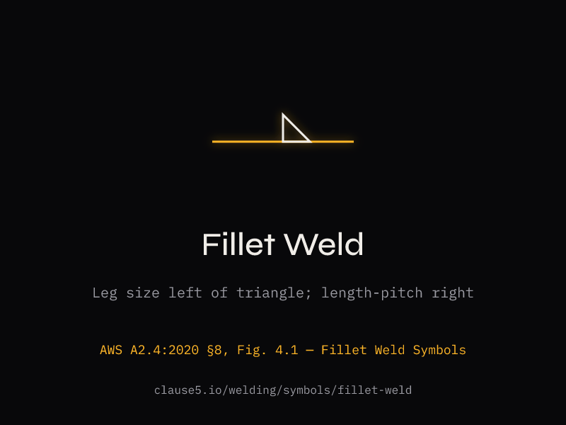
A fillet weld symbol is a right triangle placed on the reference line of a welding symbol, defined in AWS A2.4:2020 §8 (Figure 4.1). The perpendicular-leg orientation rule for the symbol comes from §6.3. The perpendicular leg of the triangle is always drawn on the left side regardless of weld orientation — this is a fixed convention, not an indicator of joint geometry. The number to the left of the triangle specifies the fillet weld leg size. AWS A2.4 gives fillet welds dedicated rules for size, length, intermittent welds, and both-side placement. They are used for T-joints, lap joints, and corner joints. When the symbol appears below the reference line, the weld is on the arrow side of the joint; above the line indicates the other side. Symbols on both sides mean weld both faces. D1.1:2025 Table 7.7 governs minimum fillet weld sizes based on base metal thickness.
How do you read fillet weld size from the symbol?
The fillet weld size appears to the left of the fillet weld triangle symbol per AWS A2.4 §8.2.1. This number is the leg length — for example, 5/16 means a 5/16-inch (8 mm) leg on the side indicated by the symbol's position relative to the reference line. If the same symbol appears on both sides of the reference line, that size applies to both sides of the joint. For unequal-leg fillet welds, both leg sizes appear to the left in the format S1×S2 — for example, 1/4×3/8 — and a drawing detail or note specifies which leg dimension applies to which member. The leg size is what the welder measures during fabrication and what the inspector verifies with a fillet weld gauge. The theoretical throat (leg × 0.707 for equal-leg 45° fillets) is used for structural strength calculations but is not shown on the symbol.
What is the difference between fillet weld leg and throat?
The leg is the distance from the root of the joint to the toe of the weld along each fusion face — this is the dimension specified on the welding symbol and measured by the inspector using a fillet weld gauge. The throat is the shortest distance from the root to the hypotenuse of the largest right triangle that can be inscribed within the weld cross-section. For an equal-leg 45° fillet weld, the theoretical throat equals the leg multiplied by 0.707. For example, a 3/8-inch leg produces a 0.265-inch throat. The throat dimension governs structural strength calculations: shear capacity equals 0.60 × FEXX × effective throat × weld length per AISC 360 Table J2.5. D1.1:2025 Table 7.7 specifies minimum leg sizes to ensure adequate throat for heat input and cracking prevention. The effective throat equals the theoretical throat for prequalified fillet welds with no deduction.
What does 3-12 mean on a fillet weld symbol?
The numbers to the right of the fillet symbol in length-pitch format indicate an intermittent fillet weld per AWS A2.4 §8.4.1–§8.4.2. The notation 3-12 means 3-inch weld segments with 12-inch center-to-center pitch. The unwelded distance between segments is pitch minus length: 12 minus 3 equals 9 inches of unwelded space. This is the single most common misread on intermittent weld symbols — the pitch is center-to-center, not the gap between welds. Intermittent fillet welds reduce heat input and distortion on long joints, which is particularly important for thin plate and built-up members. D1.1:2025 §4.13.2.1 limits maximum pitch to 24 times the thinner plate thickness, not exceeding 12 inches for built-up plate members. When intermittent welds appear on both sides, they can be chain (aligned, per §8.4.3) or staggered (offset by half a pitch, per §8.4.4).
What is the minimum fillet weld size per D1.1?
Per AWS D1.1:2025 Table 7.7, minimum fillet weld sizes are determined by base metal thickness (T): T under 1/4 inch requires 1/8 inch minimum; over 1/4 and under 1/2 inch requires 3/16 inch minimum; over 1/2 and under 3/4 inch requires 1/4 inch minimum; over 3/4 inch requires 5/16 inch minimum. Per Footnote A, T equals the thicker part joined for non-low-hydrogen processes without preheat (single-pass required), but T equals the thinner part joined for low-hydrogen processes and non-low-hydrogen with cracking prevention per Clause 6.8.4. Footnote B states the minimum fillet size need not exceed the thinner part thickness. Footnote C sets 3/16 inch [5 mm] as the minimum for cyclically loaded structures, raising the first-row 1/8 inch value rather than capping thicker-material rows. These minimums exist to prevent underbead cracking caused by insufficient heat input into thick base metal. For edges 1/4 inch or thicker, maximum fillet size is material thickness minus 1/16 inch per Clause 4.5.2.9.
What does the number next to a fillet weld mean on a drawing?
On a fillet weld symbol, the position of the number relative to the triangle tells you which dimension is being called out, per AWS A2.4 §8. The number to the left of the triangle is the fillet weld leg size per §8.2.1 — for example, 5/16 means a 5/16-inch leg. The number to the right of the triangle is the weld length per §8.3, or for intermittent welds the length-pitch pair such as 3-12 per §8.4.1. When two values appear to the left in the format S1×S2 (such as 1/4×3/8), this denotes an unequal-leg fillet per §8.2. A reference shown in the tail of the symbol identifies an external specification, process, or drawing detail rather than a numeric dimension. Reading the position — left, right, or tail — is what determines which property each number is calling out.
Where is the length of a fillet weld specified on a welding symbol?
Per AWS A2.4 §8.3, the fillet weld length is specified to the right of the weld symbol triangle when indicated. If no length appears to the right and there are no length-pitch numbers, the fillet weld extends for the full length of the joint between abrupt changes of direction per §8.3.1.1 — no separate length dimension is required. For a specific length, the dimension is shown as a single number to the right: for example, a 1/4 to the left and a 12 to the right means a 1/4-inch fillet weld 12 inches long. For intermittent welds, length-pitch format applies per §8.4.1–§8.4.2 — 3-12 means 3-inch weld segments at 12-inch center-to-center pitch. When length information cannot fit on the symbol, A2.4 allows the dimension to be referenced from a drawing detail or note.