Stitch Weld Symbol
"Stitch weld" is a field term — AWS A2.4 calls it an intermittent fillet weld. No special symbol exists. The standard fillet weld triangle with length-pitch notation to the right is all that appears on the drawing.
§8.4.1–§8.4.2How to Read the Symbol
The intermittent fillet weld symbol uses the same right triangle as any fillet weld. The intermittent character is specified entirely by the notation to the right of the symbol. Per A2.4 §8.4.2, the pitch is specified to the right of the length dimension following a hyphen.
| Element | Position | Meaning | Citation |
|---|---|---|---|
| 3/16 | Left of symbol | Fillet weld leg size (3/16 in) | §8.2.1 |
| △ | On reference line | Fillet weld symbol — right triangle, perpendicular leg on left | §6.3 |
| 2 | Right of symbol | Weld segment length (2 in) | §8.3.1 |
| 6 | After hyphen | Center-to-center pitch (6 in) | §8.4.1, §8.4.2 |
Figure 8.2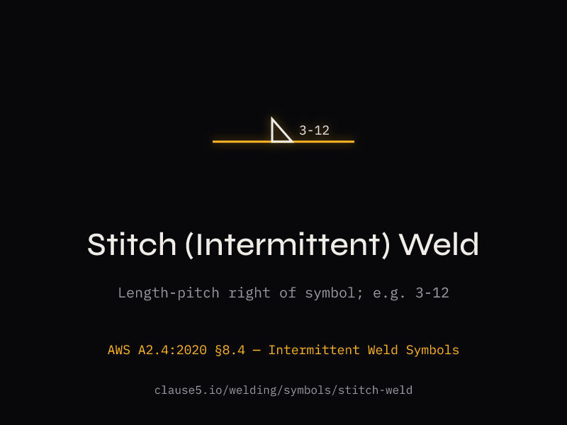
Pitch vs Unwelded Distance
The single most common misread on intermittent fillet weld symbols is treating the pitch number as the gap between welds. It is not.
§8.4.1Pitch = center-to-center distance between adjacent weld segments on one side of the joint.
Unwelded distance = pitch minus weld segment length.
For a 2-6 symbol: 2 in welds, 6 in pitch, 4 in unwelded distance between segments. AWS A2.4 does not use the word "gap" — pitch is the governing design parameter throughout the standard.
| Notation | Weld Length | Pitch (c/c) | Unwelded Distance |
|---|---|---|---|
| 2-6 | 2 in | 6 in | 4 in |
| 3-12 | 3 in | 12 in | 9 in |
| 50-150 mm | 50 mm | 150 mm | 100 mm |
§8.4.3–§8.4.4Chain vs Staggered Intermittent Fillet Welds
When intermittent fillet welds appear on both sides of a joint, they are either chain or staggered. The symbol tells you which.
§8.4.3Segments on both sides of the joint are directly opposite each other. Symbols appear aligned on both sides of the reference line, per the general alignment rule in §6.2.3.1.
§8.4.4Segments on opposite sides are offset by half a pitch — symmetrically spaced on both sides of the joint. Symbols are staggered on the reference line. This is an explicit exception to the §6.2.3 alignment rules, stated in §6.2.3.1 and §6.2.3.2.
Staggered welds produce less concentrated heat input at any single cross-section, which can be beneficial for distortion control on thin plate. Chain welds are simpler to lay out and inspect. Neither is inherently superior — the drawing specifies which applies.
§4.13.2Maximum Pitch Requirements
D1.1:2025 §4.13.2 sets maximum longitudinal spacing for intermittent welds in built-up members. These limits prevent buckling between weld points. The governing limit depends on the member type.
| Member Type | Maximum Pitch | Citation |
|---|---|---|
| Built-up plates — plate to component | 24 × thinner plate thickness, max 12 in [300 mm] | §4.13.2.1 |
| Built-up — rolled shapes to rolled shapes | 24 in [600 mm] | §4.13.2.1 |
| Compression members — outside plate | Lesser of 12 in [300 mm] or t × 0.730√(E/Fy) | §4.13.2.2 |
| Weathering steel (unpainted, exposed) | 14 × thinner plate thickness, max 7 in [180 mm] | §4.13.2.3 |
The §4.13.2.2 limit for compression members is not a flat 12-inch cap. The governing limit is the lesser of 12 in or plate thickness times 0.730√(E/Fy). For A36 steel (Fy = 36 ksi, E = 29,000 ksi): 0.730√(29000/36) = 0.730 × 28.4 = 20.7 × t. The 12 in cap governs for thick plate; the formula governs for thin plate. Always calculate both and use the smaller value.
The length and pitch values shown on the drawing must match the procedure specification — the WPS defines the actual welding parameters, travel speed, and technique that produce the specified intermittent pattern.
"Stitch weld notation is the most common source of drawing misinterpretation in structural steel fabrication. The pitch dimension is center-to-center, not the gap between weld ends."
— Widely cited in structural detailing training, reflecting AWS A2.4Section 8.4.2and D1.1:2025Clause 4.13.2
Stitch Weld Questions
§8.4.2. For example, 3/16 2-6 means a 3/16-inch fillet weld in 2-inch segments at 6-inch center-to-center pitch. The term "stitch weld" persists in fabrication shops because it is descriptive — the weld segments resemble stitching — but using it on engineering drawings or in formal welding documentation can cause confusion because it has no code-defined meaning.§8.4.1–§8.4.2. For example, 2-6 means 2-inch weld segments at 6-inch center-to-center pitch. The unwelded distance between segments is calculated as pitch minus length: 6 minus 2 equals 4 inches of unwelded space. The weld size appears to the left of the fillet triangle symbol as usual, per §8.2.1. This is the most commonly misread dimension on intermittent weld symbols — many fabricators incorrectly interpret the pitch number as the gap between weld ends rather than the center-to-center spacing. Getting this wrong results in either too much welding (increasing cost, heat input, and distortion) or too little welding (violating the design intent). D1.1:2025 §4.13.2 sets maximum pitch limits that the designer must observe: 24 times the thinner plate thickness, not exceeding 12 inches for built-up plate members.§8.4.3, have weld segments on both sides of the joint positioned directly opposite each other. The symbols align on both sides of the reference line per the general rule in §6.2.3.1. Staggered intermittent welds, defined in §8.4.4, have segments on opposite sides offset by half a pitch so that a weld segment on one side falls at the midpoint between segments on the other side. The symbols are drawn staggered on the reference line — this is an explicit exception to the normal alignment rules, stated in §6.2.3.1 and §6.2.3.2. Staggered welds distribute heat input more evenly along the joint length, reducing localized distortion on thin plate. Chain welds are simpler to lay out, mark, and inspect. Neither arrangement is inherently superior — the engineer specifies which one based on the structural and fabrication requirements of the connection.§4.13.2 sets maximum pitch requirements to prevent local buckling between weld segments. For built-up plate members per §4.13.2.1, maximum pitch is 24 times the thickness of the thinner plate joined, with an absolute cap of 12 inches (300 mm). For two or more rolled shapes connected by intermittent welds, the limit is 24 inches (600 mm). For compression members per §4.13.2.2, the limit is the lesser of 12 inches or plate thickness times 0.730√(E/Fy) — for A36 steel (Fy = 36 ksi, E = 29,000 ksi), this formula yields 20.7 times the plate thickness, so the 12-inch cap governs for thicker plate. For unpainted weathering steel per §4.13.2.3, maximum pitch tightens to 14 times the thinner plate thickness, not exceeding 7 inches (180 mm), to prevent moisture entrapment between segments that could accelerate corrosion.§8.4.1. The unwelded distance (sometimes informally called the "gap") between segments equals pitch minus the weld segment length. For a 2-6 notation: 2-inch weld segments, 6-inch center-to-center pitch, 4-inch unwelded distance between segment ends. If a welder misreads pitch as gap, they place welds 8 inches apart (2 + 6) instead of 6 inches — resulting in 33% less weld than designed. AWS A2.4 does not use the word "gap" anywhere in its intermittent weld provisions. Pitch is the sole governing dimension for both symbol interpretation and D1.1:2025 §4.13.2 maximum spacing compliance.